
 CenterClick NTP200 and NTP250 Documentation - Hardware
Main
Docs
o Features
o Hardware
o Software
o Getting Started
o Release Notes
o Front Panel Button
o Front Panel LEDs
o USB Console
o Admin CLI
o Using HTTPS
o SSH Authentication
o Client List
o Antenna Issues
o Graphs
o PPS Output
o Reimage
Live Demos
Contact Us
Feedback and Bug Reports
Follow us on LinkedIn
Privacy Policy
Shipping and Tax
Returns and Warranty
Hardware Overview
The NTP200 and NTP250 feature a small form-factor measuring about 4.25" x 2.5" x 1".
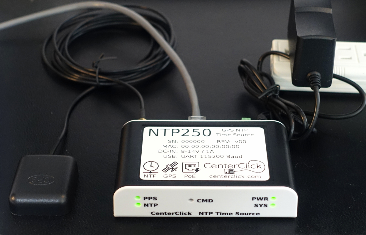
The front panel contains:
- PPS and NTP LEDs
- The command button (recessed)
- Power and System LEDs
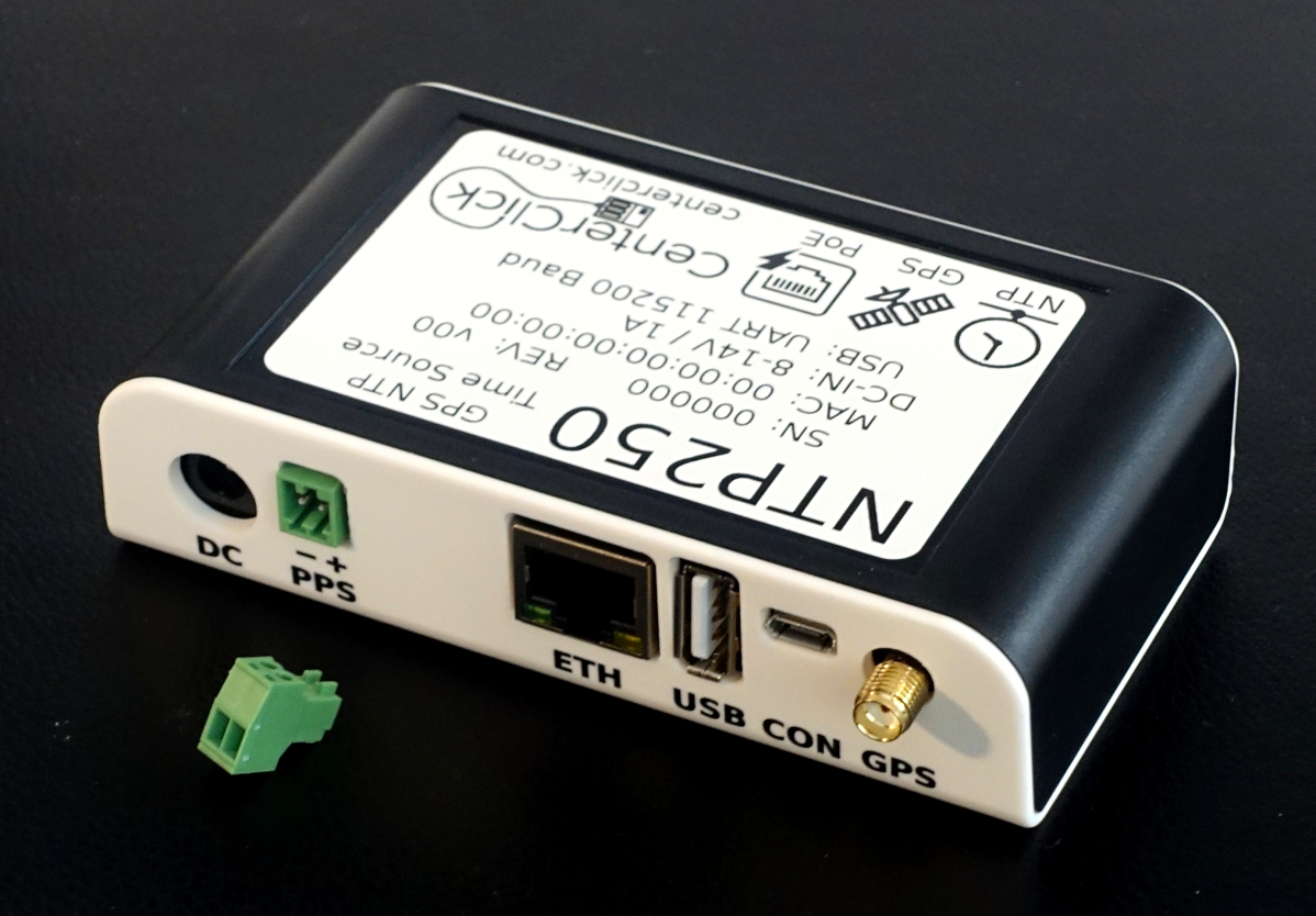
The back panel contains all connections:
- DC Power input - 5.5mm/2.1mm or 5.5mm/2.5mm barrel connector
- PPS Output - 2-pin terminal block
- Ethernet - 10/100mbps
- USB-A - Offline software upgrade
- USB-MicroB - Local console configuration
- GPS Antenna - SMA connector
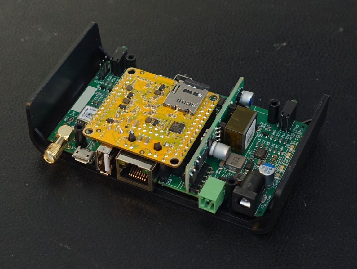
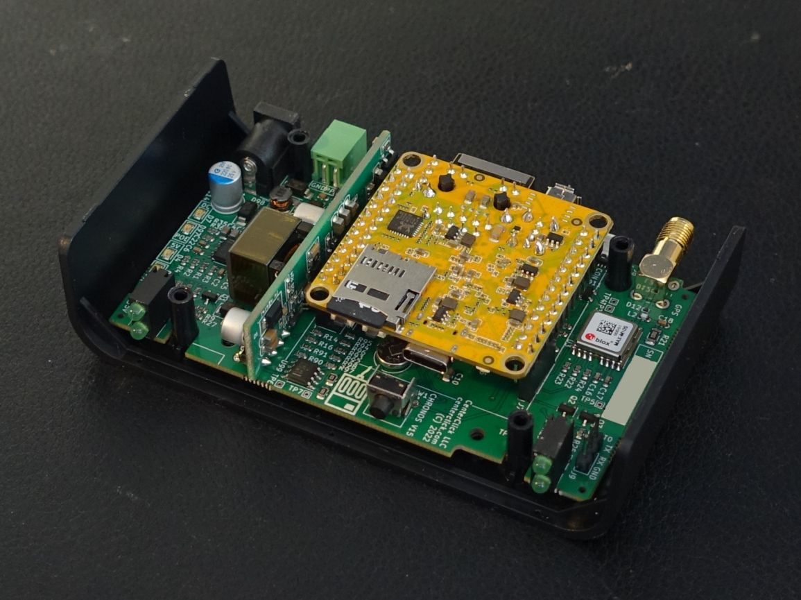
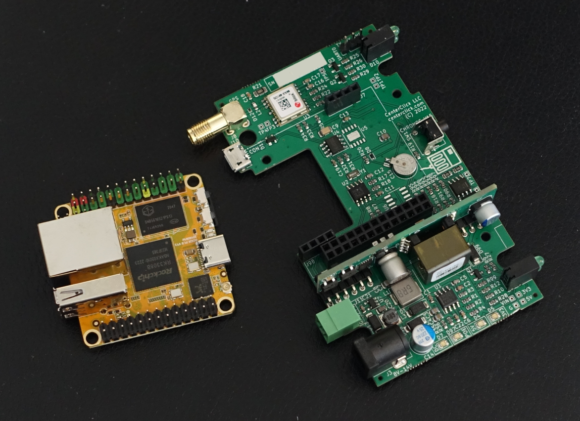
Hardware Architecture

The NTP200 and NTP250 are based on a dual PCB design as shown below. The yellow top board is an embedded ARM SoC compute module and the green base board contains power supplies the GPS module and other items. A lot of value is packed into its tiny case.
CPU, RAM, and Storage
The NTP200 and NTP250 use a multi-core ARM SoC from Rockchip.
All NTP250's have 512MB of RAM, and most NTP200's have 256MB of RAM (in mid-summer 2021, some NTP200's shipped with 512MB due to part shortages).
All boards ship with an 8GB or 16GB MicroSD card.
GPS Module & Antennas
In Hardware version 14 and before, the NTP200 and NTP250 use a uBlox MAX-M8Q GPS Module.
In Hardware version 15 and 16, the NTP200 and NTP250 use a uBlox MAX-M10S GPS Module
In Hardware version 17 and later, the NTP200 and NTP250 use a Quectel L76-L GPS Module
An active 3.3V powered antenna is supported. The Antenna is powered as described in Figure 8 on Page 12 of the u-blox M8 Hardware Integration Manual.
USB Admin Console
The Micro-B USB connector is controlled by a WCH CH340 UART to USB adapter. This port is configured for 115200 N81 serial communication.
Power Supplies and Backup
The NTP200 takes a single external DC power supply input where as the NTP250 can be powered by dual inputs (DC input and PoE). The NTP250 has hardware fail-over between the 2 inputs. Power consumption is around 1 Watt.
The GPS module and RTC are powered by a rechargeable supercapacitor. If the power inputs are lost during a power outage or are temporarily disconnected. The GPS module and RTC will remain powered for about 3+ hours allowing for a quick re-acquisition of the GPS signal in just seconds instead of 30-90 minutes on a cold boot. The supercap will charge from 0% to 90% in about 20 minutes.
| HW Rev <= 10 | HW Rev >= 11 | |||
|---|---|---|---|---|
| NTP200 | NTP250 | NTP200 | NTP250 | |
| DC Power Input (2.1/5.5mm barrel connector) | 7-14V DC 9V-1A or 12V-1A recommended |
7-11V DC 9V-1A recommended |
8-14V DC 9V-1A or 12V-1A recommended |
|
| 802.3af/at PoE | - | Yes | - | Yes |
| Dual Redundant Power Inputs | - | Yes (DC + PoE) | - | Yes (DC + PoE) |
| Priority when both DC+PoE Powered | - | PoE | - | When DC <12V: PoE When DC >12V: DC |
Hardware Revisions
Hardware Rev 6 & 7 & 8
- First production boards
Hardware Rev 9 & 10
- Add DC-IN reverse polarity, over-voltage, and ESD protection
- Improve DC-IN power supply filtering
- Switch console UART from CH340G to CH340N
- Connect GPS I2C pins to CPU
Hardware Rev 11
- Add brownout protection on VIN, increase minimum from 7V to 8V
- Add bulk CAP to DC-IN
- Add PoE minimum load
- Add PoE load when DC-IN > 11.5V
- Increase maximum DC-IN for NTP250 from 11V to 14V
- Decrease brightness of on-board 5V and 3V3 LEDs
- Increase supercap charging rate by 20%
- Assemble console UART with either a CH340N or CH340K
- Add ESD protection to GPS antenna connector
Hardware Rev 12 & 13 & 14
- Improve DC-IN power supply filtering
Hardware Rev 15 & 16
- Switch from uBlox MAX-M8Q to MAX-M10S
- Add 5V PPS output on a pluggable terminal block connector
Hardware Rev 17
- Switch from uBlox MAX-M10S to Quectel L76-L
- Add EEPROM for board info and stats storage