

 CenterClick NTP Series Documentation - Antenna
Main
Store
NTP Docs
o Features
o Hardware 200/250
o Hardware 220/270
o Getting Started
o Release Notes
o Front Panel Button
o Front Panel LEDs
o USB Console
o Admin CLI
o Using HTTPS
o SSH Authentication
o Client List
o Antennas
o Troubleshooting
o Graphs
o PPS Output
o Reimage 200/250
o Reimage 220/270
GPS14x Docs
Live Demos
Contact Us
Feedback and Bug Reports
Follow us on LinkedIn
Privacy Policy
Shipping and Tax
Returns and Warranty
Antenna Options
Antennas Supplied by CenterClick
We offer 2 antennas, an indoor rated puck antenna with magnetic base and an outdoor rated antenna with 2 different mounting bases. The outdoor antenna can be purchased with either a 5 meter or 10 meter cable.
We individually test every antenna we sell. Each antenna is tested in a RF isolation chamber and receives signals from our GPS simulator equipment to test receive strength.
Looking to mount a single outdoor antenna but connect multiple devices? We offer several GNSS antenna splitter devices.
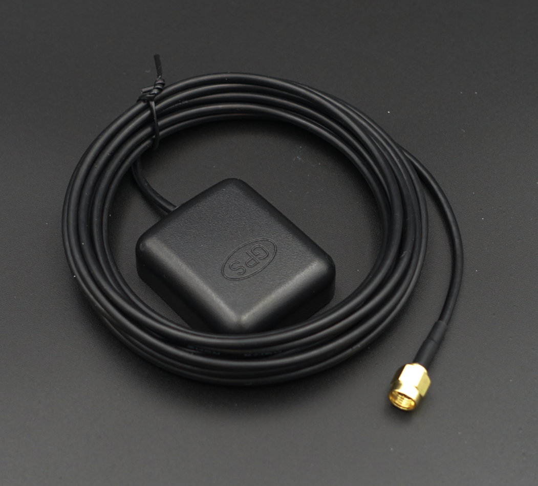
Indoor Antenna
Our indoor antenna is general purpose and is water-resistant, but not water-tight.
It includes a 3 meter RG174 cord and a magnetic base. In most cases this GPS antenna can lock to satellites from indoor environments.
Acquisition time is very dependent on signal strength, the best location for the antenna is near a window or edge of the building. Avoid placing it near metal cabinets, inside metal racks, or near equipment or HVAC ducting above. Also make sure the antenna puck isn't covered and place it on top of sheet metal to provide a good RF ground plane.
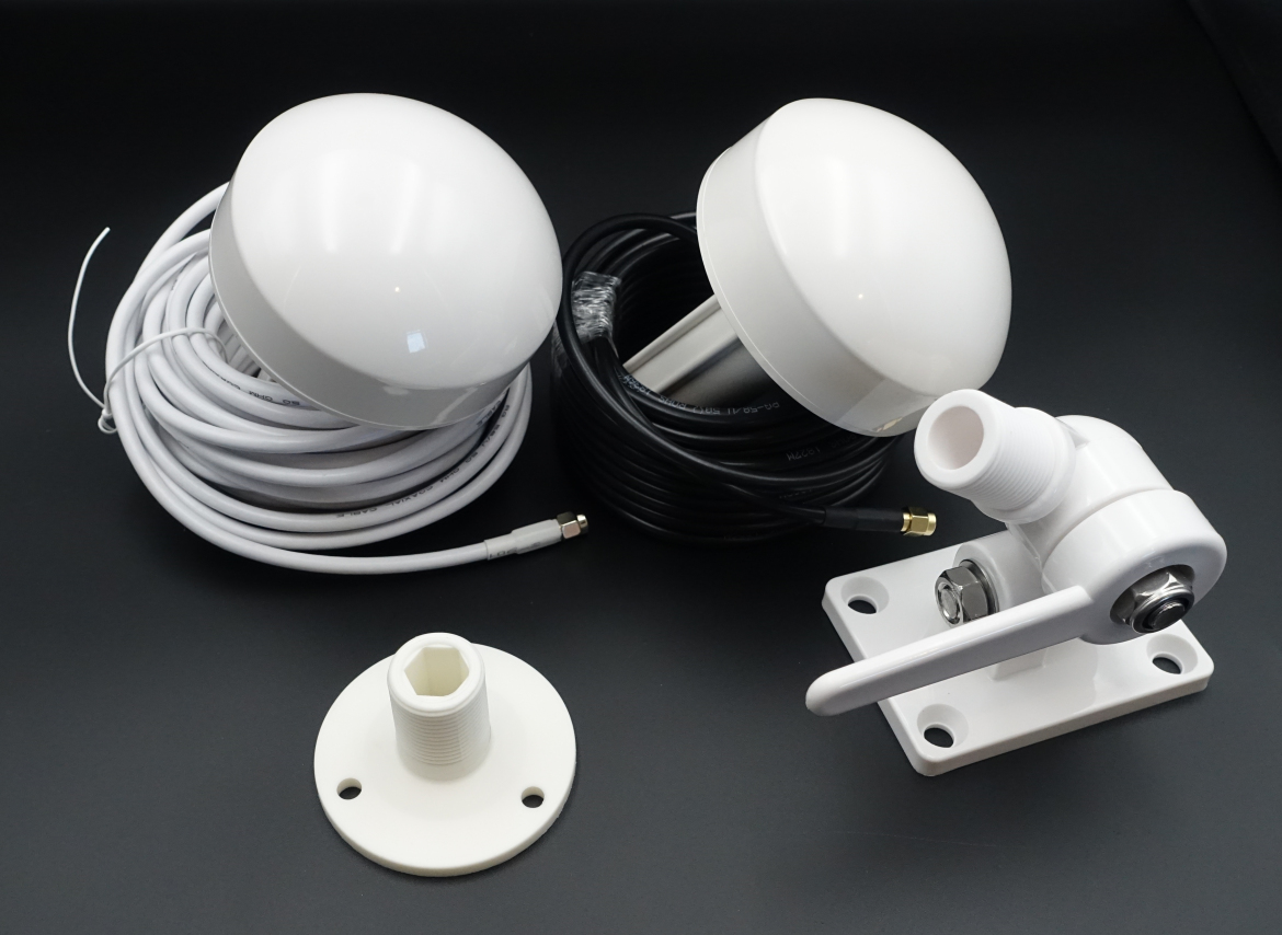
Outdoor Antenna with Fixed base
If your building will not accomidate our Indoor Antenna, we offer an outdoor rated antenna with a fixed mount for mounting on a flat horizontal surface.
We offer both 5 meter and 10 meter RG58U cords and a screw-on base. Mounting screws are not included.
NOTE: The outdoor antenna cable may be white or black, we have a mix of these.
Outdoor Antenna with Multi-Axis base
If you need to mount to a side of a building, pitched roof, or other non-horizontal surface, we offer an outdoor rated antenna with a multi-axis adjustable mount.
We offer both 5 meter and 10 meter RG58U cords and a screw-on base. Mounting screws are not included.
NOTE: The outdoor antenna cable may be white or black, we have a mix of these.
Alternative Antennas
There are a variety of antennas available for purchase elsewhere, the following hard requirements are needed when picking an antenna:
- Be a powered or 'active' antenna, typically these will be listed as having around 28dB gain, and/or a built-in LNA/SAW.
- Accept 3.3V power over the antenna cable, for example an antenna may accept a voltage range of 3V-5V or 2.5V-5V or 2.5V-3.6V which all would be acceptable, however an antenna requiring 12V would not.
- Be tuned for 'GPS L1' frequency (1.575Ghz), however it may also list GLONASS/Galileo/BAIDU/etc.. all of which are in the 1.55-1.62Ghz range. A WiFi or Cellular antenna will not work.
- Have a SMA male connector (or adapter)
- Use 50 Ohm Impedance cable (usually RG174 or RG58)