

 CenterClick NTP Series Documentation - Hardware
Main
Store
NTP Docs
o Features
o Hardware 220/270
o Hardware NTP3xx
o Getting Started
o Release Notes
o Front Panel Button
o Front Panel LEDs
o USB Console
o Admin CLI
o Using HTTPS
o SSH Authentication
o Client List
o Antennas
o Troubleshooting
o Graphs
o PPS Output
o Reimage 220/270
GPS14x Docs
Live Demos
Legacy Products
o Hardware 200/250
o Reimage 200/250
Contact Us
Feedback and Bug Reports
Follow us on LinkedIn
Privacy Policy
Shipping and Tax
Returns and Warranty
NTP320, NTP370, and NTP390 Hardware Overview
The NTP3xx series feature a small form-factor measuring about 4.25" x 2.5" x 1".
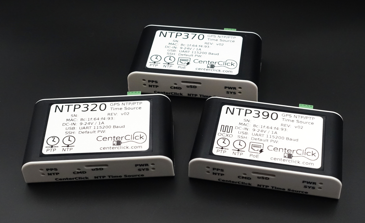
The front panel contains:
- PPS and NTP LEDs
- The command button (recessed)
- Micro-SD slot
- Power and System LEDs
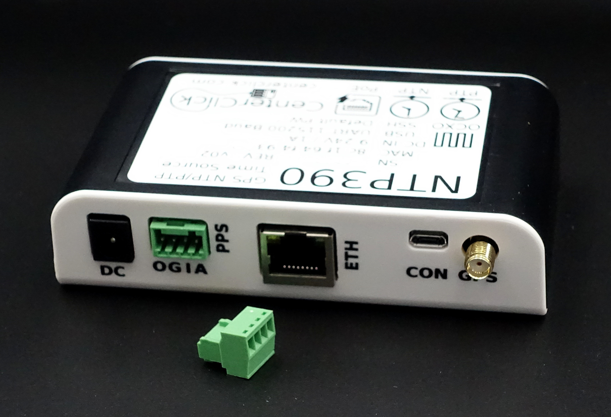
The back panel contains all connections:
- DC Power input - 5.5mm/2.1mm or 5.5mm/2.5mm barrel connector
- PPS In/Out and Aux Out - 4-pin terminal block
- Ethernet - 10/100mbps
- USB-MicroB - Local console configuration
- GPS Antenna - SMA connector
Hardware Architecture
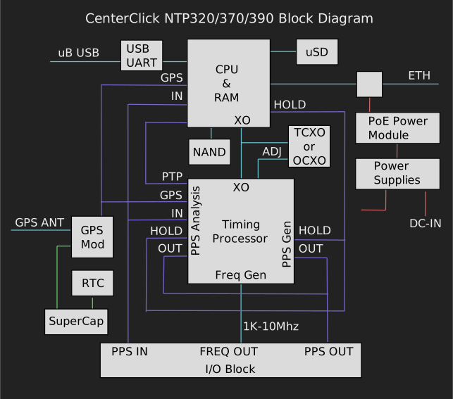
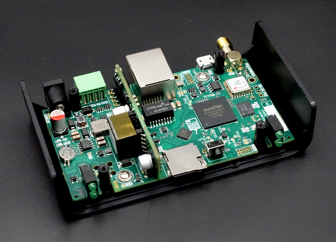
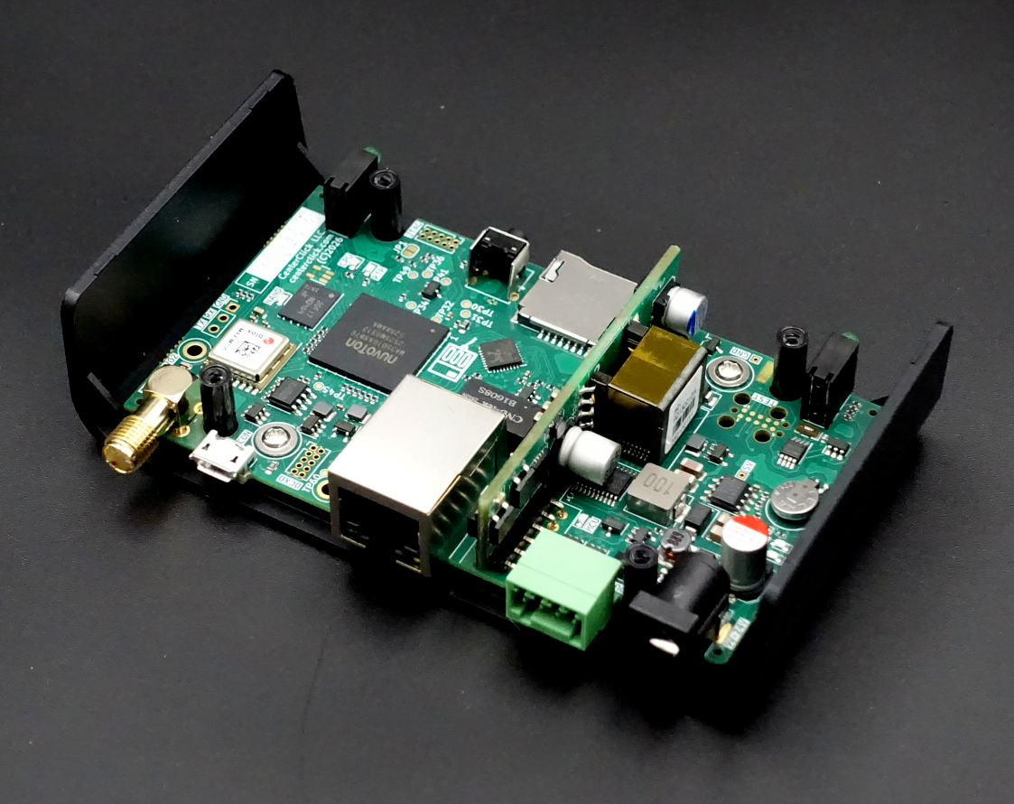
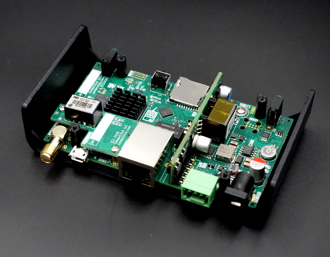
The NTP320 and NTP370 are based on a fully-integrated PCB design as shown below. A lot of value is packed into its tiny case.
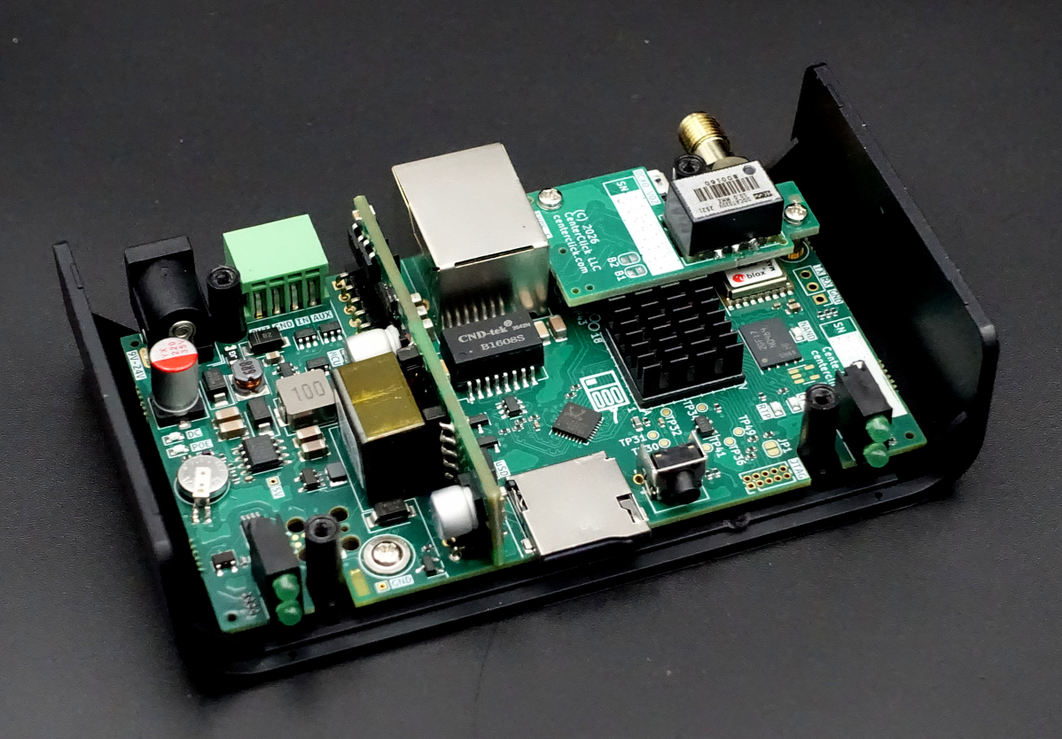
The NTP390 adds a plug-on card with an OCXO.
CPU, RAM, and Storage
The NTP3xx series use a multi-core ARM SoC from Nuvoton.
256MB of RAM is integrated with the SoC.
A 512MB SLC NAND Flash is on PCB and stores the OS image and all configruation.
The Micro-SD is available for reimaging if needed.
Realtime Processor and Frequency Source
The NTP320 and NTP370 use a VC-TCXO as the system's frequency source. A TCXO has temperature compensation to counteract most but not all of the effects temperature fluctuations have on crystal frequency sources. The NTP390 uses a VC-OCXO as the system's frequency source providing almost complete resistance to temperature fluctuations providing the most stable source.
The NTP3xx series use a real-time timing processor to perform PPS analysis, PPS generation, frequency generation, and disapline the TCXO or OCXO to counteract manufacturing differences, aging, and temperature fluctuations in the systems frequency source driving the CPU.
The timing processor generates 2 PPS signals, one for the PPS Output connector and one for holdover. The processor loops these 2 generated signals back into itself (along with the GPS and PPS Input) to analize the stability of all 4 sources.
While a GPS input is present, the timing processor will tune the TCXO/OCXO to result in a frequency source accurate to within 10-15ppb. When GPS input is lost the timing processor will use learned values to keep the frequency accurate during the holdover period.
The OCXO on the NTP390 will reach temperature within 1-3 minutes after power on, however the crystal within requires additional time to bake after a cold power-on if it was powered off for a significant amount of time (more than 1 hour). During this bake time, the timing processor will adjust it if a GPS signal is present to keep the frequency accurate but holdover is not possible until the OCXO reaches full stability which may take 1-3 days of continuous power-on time.
GPS Module & Antennas
The NTP3xx series use a uBlox MAX-M10S GPS Module
An active 3.3V powered antenna is supported.
USB Admin Console
The Micro-B USB connector is controlled by a WCH CH340 UART to USB adapter. This port is configured for 115200 N81 serial communication.
Power Supplies and Backup
The NTP320 takes a single external DC power supply input where as the NTP370 and NTP390 can be powered by dual inputs (DC input and PoE). The NTP370 and NTP390 have hardware fail-over between the 2 inputs. Power consumption is around 2-3 Watts.
The GPS module and RTC are powered by a rechargeable supercapacitor. If the power inputs are lost during a power outage or are temporarily disconnected. The GPS module and RTC will remain powered for about 3+ hours allowing for a quick re-acquisition of the GPS signal in just seconds instead of 30-90 minutes on a cold boot. The supercap will charge from 0% to 90% in about 20 minutes.
| NTP320 | NTP370 | NTP390 | |
|---|---|---|---|
| DC Power Input (2.1/5.5mm barrel connector) | 12-24V DC Nominal 9-25V DC Min/Max 12V-1A recommended |
||
| 802.3af/at PoE | - | Yes | |
| Dual Redundant Power Inputs | - | Yes (DC + PoE) | |
| Priority when both DC+PoE Powered | - | When DC <12V: PoE When DC >12V: DC |
|
Hardware Revisions
Hardware Rev 2
- No notible changes